


The issue of stealth technology has become a topic of discussion and heated debate regarding the F-35 fighter jets. The technology is seen as the future of aviation internationally but we also often see the term for warships. But what is stealth, on what principles is it based and is it really such a game changer? For airplanes it seems relatively easy now, but for warships? So let’s look at some basic principles and limitations at a level we can all understand.
Origin of the word stealth
In the English language it has its roots in the word stelthe which in the Middle Ages meant theft. Etymologically it goes back to Old German for theft, stāla. Therefore, since no successful thief would do his work when others could see him, especially in times when being caught would not have a positive effect on his prosperous life, the word became identified with the meaning of hidden or invisible business.
Basic principles behind the technology
The foundations of stealth technology are rooted in theoretical and applied physics. The practical applications in airplanes and ships combine many other specialties such as electronics, materials, etc. In theory, stealth means not reflecting the electromagnetic (EM) or mechanical wave emitted by the adversary in a direction and power that his transmitter can detect and process The return. Thus, for a fighter, the EM wave from the ground or airborne adversary radar must either be absorbed or reflected in a direction that will not reach the transceiver’s sensors. But if the principle is relatively easy to formulate, how to practically suppress or eliminate the reflection of the radar EM waves is not so simple.
What happens when an EM wave hits another medium? The law of reflection states that the angle of incidence is equal to that of reflection and on a smooth surface both rays remain in the same plane, which is perpendicular to the surface. But here some problems begin. This is shown in Figure 1(A) where the rays remain parallel even after reflection.
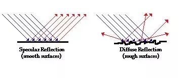
This is the ideal case of reflection (A). The laws of reflection apply to all kinds of waves and to all wavelengths, but what a smooth surface means also depends on the wavelength of the radiation. Since no surface can be perfectly smooth, the criterion of how smooth it is is compared to the wavelength of the radiation. If the surface has deviations from the ideal, it means that parallel rays do not remain parallel after reflection and not even in the same plane, so we have diffusion (B). That is, at a microscopic level the laws of reflection apply but in macroscopic space the radiation (energy) has a direction other than that expected from ideal reflection. In case (B) the rays are not even in the same plane, i.e. the surface scatters EM in all directions.
In physics, the parameter of an EM that determines its nature is the frequency, which defines the energy carried by the EM radiation. The relationship between frequency (ν) and wavelength (λ) is c=λ*ν, where c is the speed of light in vacuum. When the propagation medium for the radar waves remains the same, e.g. the air, we usually refer to wavelength because we are better aware of magnitude than frequency. Frequency determined energy is the energy carried by the EM wave that plays a role in stealth technology, and should not be confused with the radar transmit power which represents the number of waves the radar produces per second.
So the frequency (or wavelength) determines how well the target can be hidden by size, as well as the absorption in the atmosphere and the choice of materials to suppress reflection from the target. The power of the radar only guarantees that enough energy will be reflected off the target to detect and possibly target. That is, it determines the maximum distance for a given target, all other factors being equal, as discussed in Section 3.
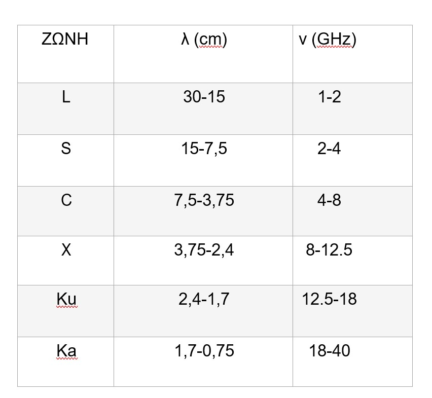
A very good example of the relationship between wavelength and target size is water and… ouzo! Both are liquid clear in the visible spectrum of light, with wavelengths from 300 nm to 700 nm (nanometers). The reason they are both colorless is because the size of their molecules is much smaller than the wavelength of light. The chance of reflection and scattering is small for the small amounts in the glass. But when the two are mixed, the result is a pure white drink! The reason is that the new molecules formed by the union of the two are now larger than the longest wavelength of light and the entire spectrum is scattered (reflected) with the same intensity. When all colors, the entire spectrum of light, are mixed equally, we end up with white. It’s the same reason milk is white. So wavelength and stealth are not independent parameters. The table here shows the wavelengths and frequencies for the radars:
With flat surfaces the design must be such that the reflection of the energy from the radar is not directed towards the transmitter. Obviously, curved surfaces should be avoided as much as possible and designed to reduce reflection in directions where the threat is coming from. Also, any variation from a smooth surface, such as sensors, protrusions and sharp edges, lead to uncontrolled reflection and are avoided.
Two of the reasons that the B-2 and the new B-21 bombers have such a low Radar Cross Section (RCS) are the lack of vertical tails and the placement of the air inlets for the engines on the upper surface. So the only surface that a radar will see from the front and bottom is the front and the ventral, the latter almost flat. Here we have the second part of the practical application of stealth technology, with the use of non-metallic materials as well as special paints that absorb a large percentage of the energy, so that it is lost to the enemy radar.
Historically, the concept of Active Cross Section originates and is widely used in Physics and expresses the probability for a certain reaction to occur. It has as a unit of measurement this area and, especially for the case that concerns us here, the Active Radar Cross Section (RCS) is expressed in m2 or in logarithmic expression dBm2. Although the reference is for surface size, the geometry relationship of the target surface and the RCS returning the EM is special. A sphere with a diameter of 1.13 m has a cross-sectional area of 1 m2 and with ν=1 GHz the RCS is 1 m2. However, a plate with a surface area of 1m2, which is perpendicular to the radar rays, reaches an active cross-section of 140 m2! The reason is simple. The sphere reflects the radiation at different angles due to its curvature and only a percentage returns to the transceiver. Conversely, at an angle of incidence of 0 to the vertical, reflection at the same angle sends (theoretically) all the radiation back. If, of course, the plate is angled off the vertical, the reflection will direct the radiation out of the solid angle of the transceiver resulting in a drastic reduction in RCS.
Ships and airborne radars use L and S bands to transmit. In fact, the second zone also has the advantage of less absorption in the atmosphere. In general, waves with a longer wavelength do not lose as much power as waves with a shorter wavelength. In addition, L, and to a lesser extent S, bands of similar wavelength, compared to the size of the aircraft, make the latter become a secondary antenna (tuning). EM radiation forms an interaction with the object and its nature is characterized by three categories, in relation to wavelength and target size:
- Rayleigh region: typical object size < l
- Tuning Area: λ < standard object size < 3λ
- Optical Reflection Area: 3l < standard object size
In the case of pure ouzo we have Rayleigh Area. It is clear that there are no strict dividing lines but these three areas define the main reflection mechanisms. Therefore detection for a fighter with an L-band radar is mainly through frequency tuning and not just by optical (geometric) reflection. This is precisely the reason why even small external loads increase the (RCS) so much, more strongly than their geometric size would justify.
Of course, for L radars to be effective, their antennas must be of large dimensions, that is, on ships, ground stations and airborne radars. The Russian Su-57 and Su-35 are also advertised as having L-band radars on their wings that are effective against enemy stealth fighters. The small size of their radar is unlikely to be effective for this purpose and is rather complementary to the IFF system, although it can also be used as an electronic collector in this band.
Paints or coatings (Radar Absorbing Materials, RAM) to suppress the reflection of radar wave energy are based on the conversion of EM into thermal. The basis of such materials is a combination of a polymeric matrix of ferromagnetic balls with a high dielectric constant (Iron Ball Paint). These absorb the EM energy and convert it into thermal energy and ultimately this leads to a small increase in the temperature of the material. In general, such materials are more effective for the higher frequencies, but efforts are also being made to create materials with a wider coverage (Broad Band). They are technologies that manufacturers keep secret, for obvious reasons.
Is it possible to design stealth ships?
If building stealth aircraft is a difficult business, designing a stealth warship sounds like an oxymoron! How do you hide a large ship from radar? Airplanes have the ability to operate in three dimensions and can use terrain or height depending on the mission and prevailing conditions. Ships, however, are doomed to two dimensions and, apart from islands, the only coverage available is the curvature of the Earth. This, however, makes the ships, when they appear on the horizon, already at a short distance from the opponent.
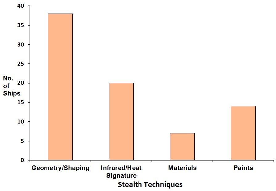
Ships to be stealth to all threats – air, surface and underwater – must suppress EM emissions from enemy radars, not emit themselves, not make noise and not leave a trail. The problem is obvious. It is almost impossible to make a warship as difficult to track as an airplane. But what must go into the design of a ship to make it very difficult to track and target? This can be seen in the image below which depicts the number of warships in use that have been applied the tactics of the scheme (a), infrared suppression (b), selection of special construction materials (c) and paint (d), respectively.
We will focus on radar suppression which is obviously the most effective way to protect the ship. Usually, of course, a combination of methods is used.
The big problem with warships is that they are not naked vessels but have a plethora of weapons and other large systems which are highly reflective to EM, and very difficult to suppress the reflection of enemy radar beams.
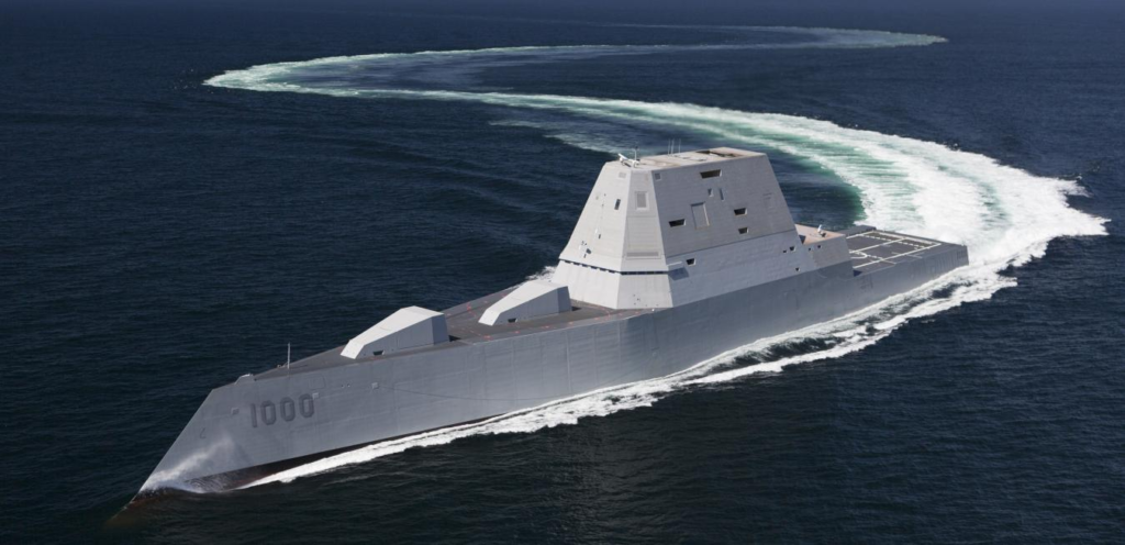
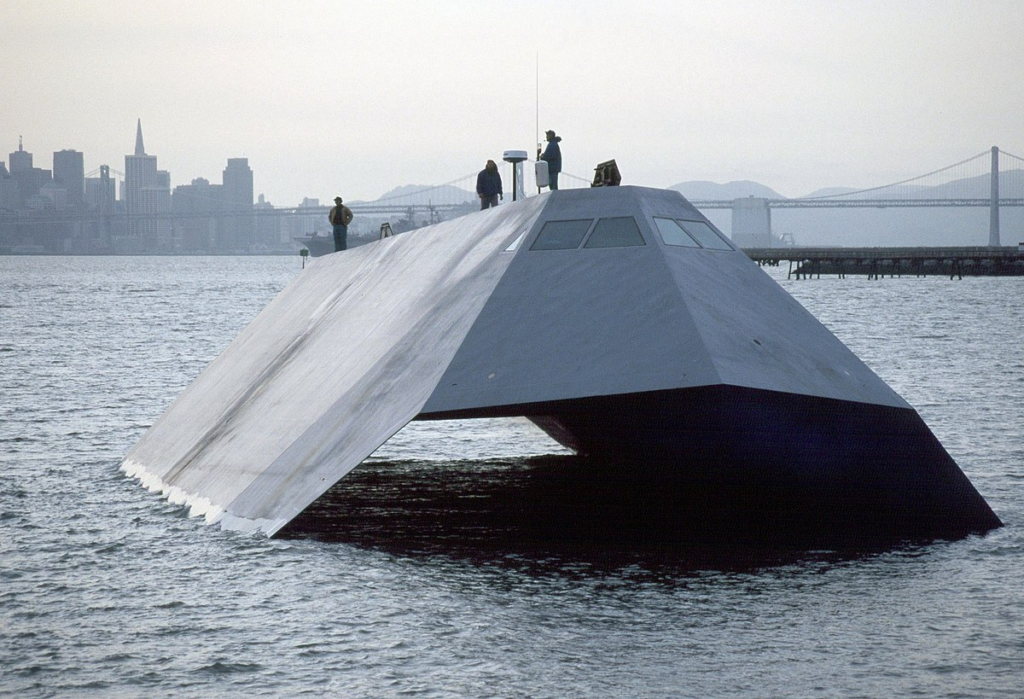
The US Navy once built and tested an experimental stealth ship, the Sea Shadow (Figure 2). The shape of the vessel was such that the large surfaces were as smooth as possible, relative to the wavelengths of naval radars. In one exercise, the ship entered a US Navy base at night, with all its lights off and none of the other ships’ radars detecting it. So at least it has been reported in press comments. Zumwalt destroyers follow the same philosophy.
It is therefore obvious that at first level the design of the ship starts from the shape of the vessel. An example is the Freedom type LCS below.
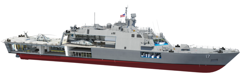
The ship may not be particularly combat-worthy in its basic configuration, but in terms of design for stealth it is a very good example. So while the boat has its sides sharply angled towards the surface of the sea, the superstructure is angled towards the sky. So combined with the lack of many beyond the cover of the superstructure, weapons systems, radars, sensors and other sources of reflection, the whole plan is considered a success. Of course, it lacks the systems that would make it well armed but for what it was designed, it satisfies the requirement of low active cross-section from enemy radars. Even the cannon has different surfaces, with slopes that reflect either the sky or the sea. This is why the French stated that adding the RAM launcher for point defense to the FDI would reduce the craft’s stealth performance.
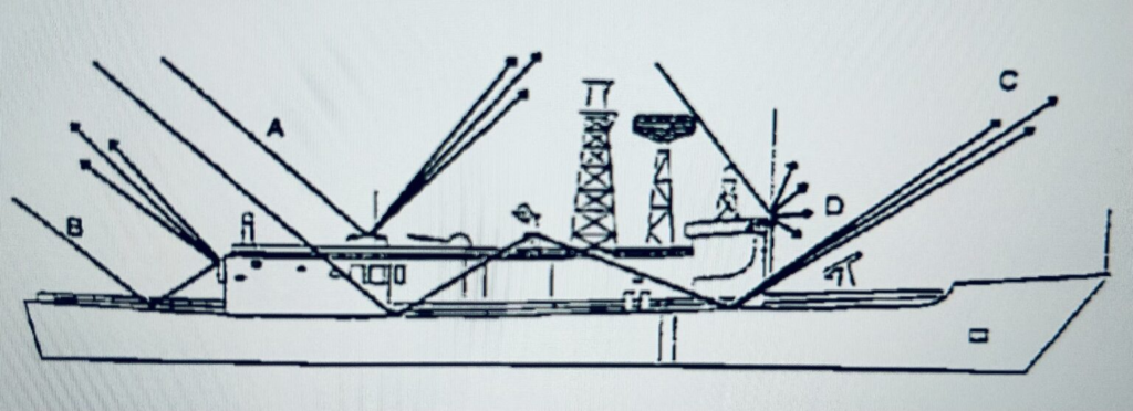
How much the systems affect the superstructure can be seen from Figure 4 where:
- A is mere reflection,
- B double, with a completely different direction from the original,
- C triple reflection and
- D scattering at a peak or corner.
Essentially the ship is returning EM energy in all possible directions, causing not only the original enemy radar to receive a strong return but possibly other enemy ships in the area as well.
Measuring and calculating the RCS of a ship is clearly not an easy task. In contrast to airplanes where measurements can be made in special chambers and/or on elevated bases so as to depict all angles, with ships this is very difficult. And they can’t have the accuracy of the counterparts for airplanes but probably with the size of the ship they don’t need those either. Studies are also done with computers, so eventually it is possible to come up with equations that produce accurate calculations. With the above caveats, an empirical, relatively parametric equation has been derived for the RCS (σ’) that relates the size (displacement) of the vessel and the radar frequency. This equation has been based on measurements from various angles and frequencies but does not reflect the true picture due to differences in onboard systems. That is, it is not the effective RCS (σ) for a certain ship, as explained below, but it does not deviate that much:
Equation 1: σ’= 52⎷(νxD3)
Here, “ν” is the radar frequency in GHz, corresponding to λ= 3.25, 10.7 and 23 cm, i.e. X, S and L bands, respectively. “D” is the ship’s displacement in thousands of tons and the equation has been tested between 2 and 17 thousand tons. For example, a 4,500 ton frigate and for the S band (10.7 cm, 3,000 MHz) we arrive at σ’ = 27,188 m2. This price is reasonable and is between the unofficially published measurements of 5,000 m2 to 100,000 m2! The frequency is in the square root, and as a result, for a large target like a ship the differences in frequencies for the other bands do not give significant differences in the result. This is to be expected because the physical size of the vessel is much larger than the radar wavelength (Optical Reflectance Area 3). The equation is indicative on a general basis of what sizes we are dealing with. It is possible that one boat has a larger s’ than another that has a better design and this is shown by the width of the measurements. How much a stealth application reduces such values is unknown in the literature, as discussed below.
Let us now consider in a slightly more detailed analysis the relationship between the effective cross-section and the distance that the vessel is detected by the enemy radar. The RCS measure in equation 1 is a static – roughly – vessel-specific measure and not the σ associated with the probability that the vessel is detected by an adversary at a distance R. In the case considered here, the probability that the adversary radar detect a target depends on the target’s actual RCS (σ), as measured under real-world conditions and with relative accuracy, accounting for radar power, weather conditions, potential electronic interference, and, of course, target-transmitter distance radar. For a certain radar, therefore, if all the parameters (except the distance) are summed up as a factor K, as a constant that is for this particular radar, the relationship between effective σ and R is (from the theory of electromagnetism):
Equation 2: σ=Κ*R4 or σ/R4=K
Equation 3: K=(4π)3*Pmin /(Pt*G2*λ2)
Where:
Pmin = power of the minimum detectable signal.
Pt = transmit power of the radar.
G = antenna gain value.
λ = emission wavelength.
So we see that to double the detection distance, σ must be 16 times larger to keep the ratio constant! The converse, of course, is true that, at half the distance, a ship with 16 times lower σ satisfies equation 2. It also shows the role of antenna power and quality in distinguishing true signal from electronic noise. State-of-the-art radars have a very low Pmin of the order of picoW (10-12 W). Equations 2, 3 generally apply, whether the object is a vessel or an aircraft.
In conclusion
While in the literature there are many publications with RCS (σ) measurements for fighters and bombers, for ships there is no similar detailed data. This observation makes one wonder why while manufacturers advertise their stealth ships as such, serious measurements are not recorded. Perhaps one reason is that determining σ on a fully equipped ship is so difficult and the results are sensitive to sea state that the measurements are not very meaningful.
It is a fact, however, that the combination of sloping sides of the vessel to direct the reflections either towards the sky or towards the surface of the sea, definitely contribute to the reduction of the radiation that returns to the enemy radar. Similar planning for the superstructure of weapons and other systems, as far as possible, is necessary but also more difficult. Paints and coating to suppress radiation from radar and infrared emissions complete the effort. However, making a fully equipped warship a very difficult target is of course impossible and, if measurements have been made on ships designed for a low probability of detection by radar, they have not been published.
As we said, an “ideal” ship, in terms of stealth capability, is the Sea Shadow in Figure 2. But it has no superstructure separate from the main vessel, and has nothing to cause the uncontrolled reflection seen in Figure 4. How much such a design is feasible for a battleship is of course an academic question.
Finally, if we calculate that the distance at which a frigate with a radar mast 40 meters above the sea surface has a horizon of about 23 km, at this distance the first indication of the target will also be. If we now assume that a low RCS frigate has a small σ= 5,000 m2, as the measurements seem to indicate, is it possible for such a frigate not to be visible on radar at 23km? Ship vs. ship, of course, is not the only case where a low p is seriously considered. It has been said, e.g. that for the US Navy, operating in the vast expanses of the Pacific and under the fear of Chinese very long-range ballistic missiles with terminal guidance, the low s of warships, where many merchant and fishing vessels sail at the same time, has an essential role in their survival.
So is the emphasis on stealth warships more fashion than effect? Between a stealth frigate ἠ/and destroyer, with all the compromises in hull design, armament and avionics required, and a classic Arleigh Burke-class destroyer with RCS that is anything but stealth, the choice will no doubt be difficult. So is stealth a luxury for warships? It depends.
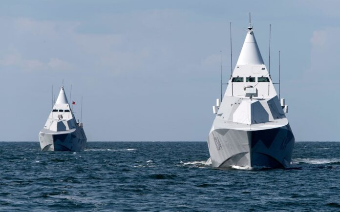
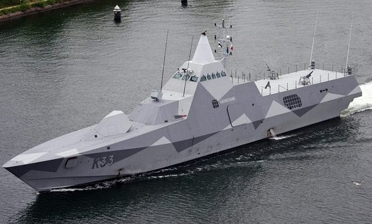
An answer has been provided with the corvette Visby (Figure 5) of the Swedish Navy, a vessel that can be described as “a floating polyhedron”. Where no thermal and EM footprint reduction technology has been left out of design and implementation. Visby, although with 20 years of trace reduction technology, is ideally designed for the Baltic: where with the presence of rocky coasts, islands and islets everywhere, it becomes a difficult environment for enemy radars, especially with effective countermeasures accompanying and optimizing all passive techniques of the vessel.
With the above, it is evident that the role stealth technology plays in concealing the ship is not as impressive as that of fighters. But there is protection of a ship with a low p. Let’s take a typical RCS and a typical relatively large frigate with a value of about 25,000 m2 (44 dBm2). With a relatively easy-to-apply paint on critical elements in the superstructure, we have a footprint reduction of 3 dBm2, so an improvement (dB scale is logarithmic) is shown at the 12,500 m2 level. By adding materials (plates) that absorb the energy of the radar rays, it is considered possible to further reduce σ by half, i.e. 6,250 m2 (38 dBm2). If now the frigate is designed properly, a final effective value σ of the order of 28 dBm2 is achievable (not easy but theoretically possible), which means about 1,000 m2!
Of course, such values are not at all small compared to fighter aircraft, but they are equal or smaller than what creates a cloud of airfoils (chaff). In other words such a track reduction increases the likelihood that the incoming missile, with its own radar activated, will go astray! Also, if the ship has capable electronic countermeasures, these work in synergy with the paints and absorption materials and reduce the distance at which the missile’s radar, which remains blinded by the electronic countermeasures, will be able to “lock” the ship as target. In combination with maneuvers and point defense shots, the ship thus has a greater chance of achieving either the failure of the missile or its destruction. For this reason the report was made, for effective countermeasures for Visby.
Conclusion: The concept of stealth for a warship has nothing to do with that of being undetectable to radar for aircraft. It is impossible to design a vessel the size of a patrol boat and above that has such a low RCS. A more accurate description is the one that says that a warship has a reduced RCS compared to another of a similar role and size.
On the other hand, a drastic reduction of the RCS can also have problems in navigation safety, because during nighttime, bad weather and generally low visibility, the safety distance to avoid collisions decreases, with all that this entails. Also, in the cost equation, monetary and design, in relation to the advantage, the need for continuous maintenance of paints and absorbent materials must also be included. Finally, in the event of war in the 21st century, a fleet cannot be expected to rely solely on radar to locate its adversary. Now there are UAVs, helicopters, airborne radars and even satellite information, so the actual offer of reducing the footprint of each vessel is reduced.
But for some cases, such as in small warships, which move between islands and islets having appropriate countermeasures, a low σ can really make a difference in survival. For a larger vessel, if weapons and electronics are not sacrificed by design, and if increased paint and tile maintenance costs are not a problem, of course low σ is definitely a strong advantage, not so much for evasion but for protection from blows. While there is value in a stealth frigate that appears to adversary radar as a fishing or other similar small merchant ship, especially in night or fog conditions.
Thus, technology and its applications in defense systems are constantly evolving and the lowness of a warship is another positive safety factor, but not a game changer, as for aircraft. Ultimately, all non-lethal defense systems against missile threats, combined with low σ, are very useful for ship survivability but are no substitute for lethal, either missiles or guns.

